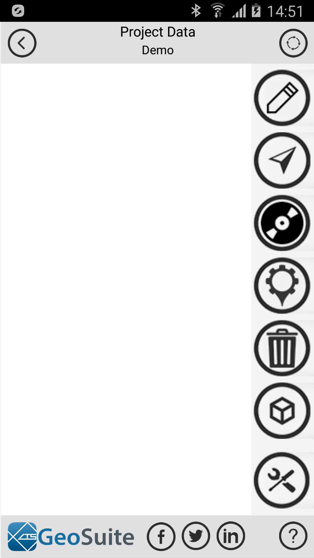
Field Tools
Select the "Field Tools" option from the point menu.

Create a single point in the field

Get GPS Location
To create a single project point in the field using GPS location data or manual location setting, select the "Line" tab. Populate the "First Point Coordinate Data" Latitude, Longitude and Altitude fields with WGS84 decimal degree data or use the "Get GPS Location" option to populate the fields with the device current GPS location.

Create single point
Select a seismic velocity model to apply to the point. Once the coordinate fields have been populated select the "Create single point from first point coordinate data". the point will then be created and added to the project point list.


Create a line of points between two field coordinates

Get GPS Location
To create a line of points in the field using GPS location data or manual location setting, select the "Line" tab. Populate the "First Point Coordinate Data" and "Second Point Coordinate Data" Latitude, Longitude and Altitude fields with WGS84 decimal degree data or use the "Get GPS Location" option, for both the first and second points to populate the fields with the device current GPS location.

Create line of points
Select a seismic velocity model to apply to the line of points and provide the number of points to be create between the two specified locations. Once the coordinate fields have been populated select the "Line between GPS locations". the points will then be created and added to the project point list.

Create a grid of points around a field coordinate

Get GPS Location
Populate the "Middle point coordinate" Latitude, Longitude and Altitude fields manually using WGS84 Decimal degrees format or populate the coordinate fields using the "Get GPS Location" option or the coordinate data from the currently selected point on the project point menu list by using the "Select existing project point" option.

Select existing project point
Select a "Grid inter-point spacing(m)" and the "Number of grid points". Then select a velocity model to apply to the grid points to be created. Lastly, select the "Create grid around point location" option to create the points. The grid points will be added to the current project point list.


Take magnetic field readings

Add magnetic reading at current location
To take magnetic field readings in the field select the "Mag" tab. To take your first reading select the "Add magnetic reading at current location" option. A message will appear requesting the user to move to the next location and repeat the process. Once the user has done so, the chart will show the magnetic field values at both locations and the distance between the two locations. This process can be repeated at multiple locations to build a magnetic field strength profile on the chart.


Record an apparent resistivity sounding
To record a apparent resistivity sounding a a location in the field, select the "Res" tab.

Select an inter electrode spacing "D" from the "Select Spacing" list then setup your feild electrodes as shown in the diagram at the top of the window. Once done, select the "Acquire apparent resistivity data" option to initiate the data collection process. Once done, the measured resistivity will be displayed on the "Apparent resistivity list to the right of the screen.

Acquire apparent resistivity data

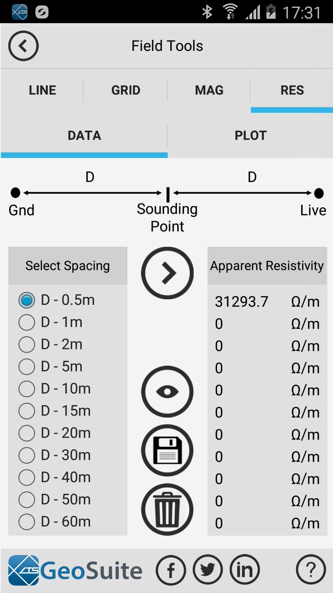
This process must be repeated until all the "Select Spacing" fields have been populated.


Render apparent resistivity data
Once all the spacing fields have been collected, press the "Render apparent resistivity data" option to render the resistivity sounding profile in the "View" tab.

The chart data will shows the apparent resistivity depth sounding data as well as the estimated groundwater table depth by the orange block on the line,

Save data to current point
To save the apparent resistivity sounding data to the selected project point on the project point menu list, use the "Save data to current point" option.

Clear data
To clear the data from the chart and the apparent resistivity table use the "Clear data" option.