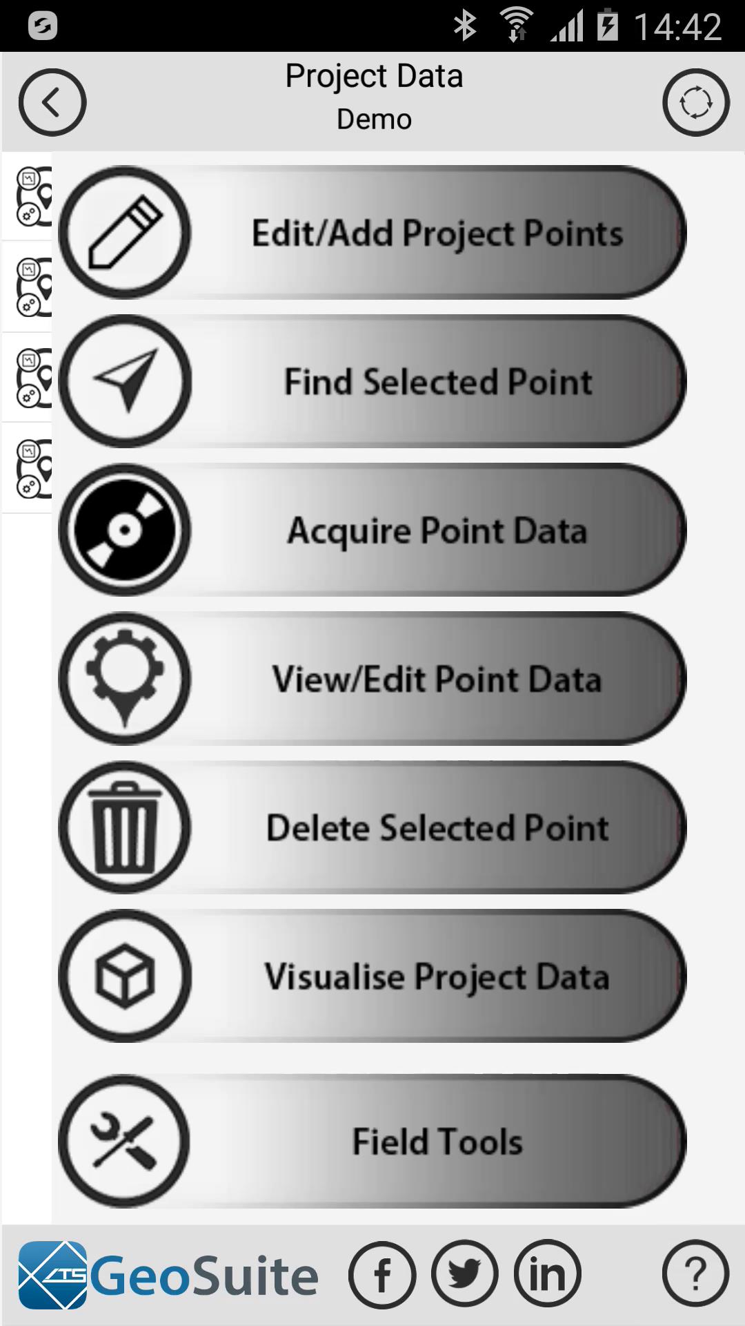
Acquire Point Data
Required Equipment

- A Smartphone device with the GeoSuite App loaded
- A sledge hammer as an entry level seismic source
- Two steel pins (Nine inch nails will work in clay based soils)
- A modified audio cable that can be constructed at home using off the shelf parts and equipment.
- An optional base plate for when you are working on very soft ground
- and some Personal protection equipment
Seismic source options
As the GeoSuite App has a software based triggering system, any impulse type seismic source can be used to collect electro-seismic data.
These include:
- A Sledgehammer ( for depths of investigation of up to 200m depth )
- A buffalo gun ( for depths of investigation of up to 300m depth )
- A 200 kg weight drop system ( for depths of investigation of up to 400m depth )
Software data acquisition process
If the user needs to acquire geophysical field data at a given location in the field, the Acquire Field Data function can be used. This can be done in one of two ways. If the project point has already been created and is shown in the Project Data list, select the point of interest on the list.


Clear Selection
If the user would like to create a new point in the field that does not already exist on the list, then the list selection must be cleared before continuing. This is done by selecting the clear list selection option on the top right of the "Project Data" menu. This will clear the project point list selection as shown below.

If no points have been created or if the point of interest does not exist on the list, simply leave the point un-selected and a point will be created for the survey location in the next step.
Select the "Acquire Point Data" option from the Project Data menu. The full menu can be seen by left swiping the Project data options bar. Right swiping will close the full option menu.


The first step in the data acquisition process is to check if the cable is functioning correctly. Connect the cable to the device then join the two clips together as shown in the diagram. Once this is done, select the "Next" option to proceed.

A warning may appear about high volume levels. If it does simply select the "OK" option.

In some cases an error message will appear when testing the Cable open resistance and calibration settings. This error message will occur under the following circumstances:
- The cable insulation is damaged
- The cable is shorting
- The cable resistor values are incorrect or out of the required specification
- The cable clamps were not separated when the test was initiated
- The device being used has an audio port that does not output at least +-0.25V peak to peak voltage. If this is the case, the app will not be able to acquire data on the device.
If the cable is damaged in some way, this can be determined using a multi-meter and following the cable testing instructions at the following link:
If the cable resistors are outside the required specifications, the cable can be tested by following the instruction at the following link:
If the device requires calibration, the device can be calibrated by following the instructions at the following link:

If the cable open resistance test completes successfully then the following menu will appear.

Now join the two clips together as shown in the diagram. Once this is done, select the "Next" option to proceed.

In some cases an error message will appear when testing the Cable closed resistance. This error message will occur under the following circumstances:
- The cable has a open circuit break on one of the cable leads
- The cable resistor values are incorrect or out of the required specification
If the cable is damaged in some way, this can be determined using a multi-meter and following the cable testing instructions at the following link:
If the cable resistors are outside the required specifications, the cable can be tested by following the instruction at the following link:

Skipping cable testing

The user may choose to skip testing the cable, however, this is not advised as the recorded data quality cannot be confirmed. To skip the cable testing functions use the "Skip Cable Testing" option on the cable test menu.


If the cable is tested to be in good working order, setup the survey point as illustrated. Place a seismic source plate directly above the location you wish to collect data at. Insert two steel or stainless steel electrode pins into the ground, exactly 2m apart, in an EAST/WEST direction. The pin closest to the seismic source plate should be no more than 20cm from the plate and no less than 10cm from the plate. Both electrodes must be inserted into the ground so that a good, firm, electrical connection is made between the ground and pin. The pins cannot be loose or wobbly to the touch. Generally speaking, 9 inch nails are perfect for most surveys, however, longer pins may be required if working on sandy soil types. Now connect the "Black" ground cable clip to the electrode pin nearest to the seismic source plate. The "Red" recording pin should be connected to the electrode pin furthest from the seismic source plate.
Lay the phone down, on a firm level surface, between the two electrodes such that the top and bottom of the phone points in a north/ south direction
Note :
- It is preferable not to conduct a survey during or immediately after heavy rains.
- It is preferable not to conduct a survey near power lines or electric fences.
- It is preferable not to conduct a survey when lightning is present nearby the survey site.
- It is preferable not to conduct a survey in highly water saturated soils.
- It is preferable not to conduct a survey on sandy soils such as riverbeds or beaches. If such a survey is not avoidable, use longer electrodes inserted deeper in to the soil to improve electrical coupling to the ground.
- It is preferable not to conduct a survey on highly rocky soils. If such a survey is not avoidable, use longer electrodes inserted deeper into the soil to improve electrical coupling to the ground.
- It is preferable not to conduct a survey on soils with high organic material content. If such a survey is not avoidable, use longer electrodes inserted deeper into the soil to improve electrical coupling to the ground.
- It is preferable not to conduct a survey within city limits as there is usually high electrical noise content within cities that may adversely affect the results of a survey. If such a survey is not avoidable please keep in mind that higher noise levels may be present and adjust your interpretation of the data accordingly. Alternatively, have a professional ES geophysicist evaluate the data on your behalf.
A typical survey setup may look similar to the image below.

Please ensure that all Operational, Health and Safety requirements for your country and/or State are followed when collecting data and that all Personal Protection Equipment recommended for the use of the ATS Geosuite Software data acquition is used during the collection of data process.
When the survey setup is complete, select the "Next" Button to continue.

The survey location will then be analyzed for noise content and the soil resistivity will be determined.

Once the survey sites noise evaluation is complete, the data will be shown in the Point Noise Statistics Window on three charts:
- Background Noise Time Series - This data set shows three seconds of site background noise time series data. Any periodic or non-periodic noise will be visible on this chart. In the case of the chart below, non-periodic electric fence noise is shown on the chart for the site.
- Background Noise Frequency - This data set shows the frequency domain representation of the site noise recorded for a period of four seconds.
- Background Noise Statistics - This data set shows the site background periodic noise statistics as a set of predefined values sets, including:
- Fundamental power line noise frequency amplitude
- Power line noise odd harmonic group amplitude
- Power line noise even harmonic group amplitude
- High frequency group amplitude
- For all the above statistical data sets the following risk color grading applies:
- Red - High levels of noise detected (Usually considered as unacceptable
- Yellow - Medium level of noise detected (Usually considered as acceptable with risk)
- Green - Low level of noise detected (Considered as acceptable and low risk)

Snapshot Icon
A snapshot tool is available that allows the user to save images of the individual charts to the Documents directory on the device in PDF format.
To proceed, select the "Next" button to continue.

If the user accepts that the sites noise characteristics are of an acceptable level for the project, the equitation of data can begin. Simply lay the phone down between the two electrodes such that the top of the phone points in a north/ south direction.

Next
Then select the "Next" option
The following menu will appear.


Settings
Additional data acquisition settings are available to the user by selecting the "Settings" option.


The settings option allows the user to apply the following options:
Normalize Data
- The user may choose to normalize the recorded data in order to correct for any variation in inconsistent seismic event power levels generated by the seismic source. To do this the use may select the "Normalize Data" option.
Remove Co-Seismic Effects
- If the user suspects that the geology on the site contains a strong seismic reflector in the shallow subsurface, the user may choose to apply the "Remove Co-Seismic Effect" feature. This feature will attempt to filter out any co-seismic energy echo effects returned to the surface though the reflection of the seismic wave by a acoustically restive interface. This feature can be deselected at a later stage. Warning - this feature should only be used if Co-Seismic effects are actually present.
Remove Co-Seismic Ground Role Effects
- If the user suspects strong ground role effects will be present on the survey site, the user may choose apply the "Remove Co-Seismic Ground Role Effects". This filter will attempt to remove any ground role generated Co-seismic energy from the data set. This feature can be deselected at a later stage. Warning - this feature should only be used if Co-Seismic Ground Role effects are actually present.
Apply Non-periodic noise Filters
- If the user has determined that non-periodic noise is present on the site, then the user may choose to apply filter to attempt to remove the non-periodic noise from the data sets. This is done by activating the filters using the checkbox on the "Acquire data Settings" menu. Warning - Applying these filters may cause loss of vertical resolution in the GeoSuite data sets. the user should only use these data sets when absolutely necessary.
Apply Seismic Attenuation Correction
- If the user is conducting a survey deeper than 200m then the user may select the "Apply Seismic Attenuation Correction" feature. This option will attempt to compensate for the energy losses caused by seismic wave attenuation at depth. This feature can be deselected at a later stage. Warning - this feature amplifies noise content on the data set as well as ES content. This feature should only be used by users with experience in Electro-Seismics.
Apply Custom Filters
- Should the user prefer to use custom filters instead of the standard filters applied to the recorded data set, then the "Apply Custom Filters" option must be selected on the settings menu. The "Apply Custom Filters" option provides the user with 20 notch filters and 1 low-pass filter to apply in any quantity, frequency or bandwidth the user chooses.
Timer Counter Setting
The user may at any time adjust the data acquisition time that the app collects data in the field for. This timer may be set to any of five, pre-defined settings, with lengths of:
40 seconds (default)
60 seconds
90 seconds
120 seconds
or 180 seconds
Adjusting the timer length will affect the application operating performance as more data will need to be processed during the acquisition process

Settings
To return to the "Acquire Data" menu, simply select the setting option again.
Then press the "Start" label to start recording data.

Data will be collected within a 40 Second period, on the default timer setting. This time frame will be indicated by a countdown clock and must not be interrupted in any way for the duration of the 40 second recording. During this recording period, the user must strike the source plate with a sledge hammer or other appropriate impulse type seismic source, a minimum of 5 times or a maximum of 20 times.

Once the 40 second recording process is complete, a series of processing algorithms will analyses and process the data for geophysical data extraction.
Each step is fully automated, however, the progress of each step is shown
The processes performed are shown in order:
- The data is filtered
- The data noise is evaluated
- The Electro-magnetic data is evaluated
- The data is extracted
- The data is correlated
- Finally, the data is rendered


Note - If the device screen saver is set to a duration that is shorter than the time it took to complete the data acquisition, the device screen will immediately go to sleep after the the data acquisition process is complete. The reason for this is that the app disables the device screen sleep mode for the duration of the data acquisition process. Once complete, it with turn the screen sleep mode again. If the sleep timeout has already occurred, then the device screen will immediately turn off. Simply touch the screen to reactivate the device and app. This is part of the normal operation of the GeoSuite Application.
When all the data analysis is complete, It will be displayed in the "Point Data" menu. Everything relating to the raw, unprocessed data is viable in this menu.


If the data is acceptable to the user then the "Accept" option must be used to save the data to the project point.
